Công nghệ LiFi, Công nghệ VR
IEEE standard – S2-PSK A choice for RoI-Signaling based Augmented Reality
S2-PSK is an operating mode being standardized at IEEE 802.15.7m. This post describes what it is for and how it operates.
Technical Considerations for a RoI-signaling Waveform
Even though RoI-signaling mode has a very low data rate, it is indispensable to the OCC system operating in a challenging condition such as V2X.
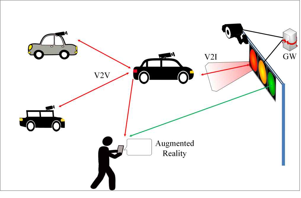
The general technical considerations have been addressed in the previous post. In this section, particular considerations and requirements for a low-rate RoI signaling waveform are discussed. Providing the low-rate data transfer mode, a proposed RoI signaling technique is intended for either a challenging V2V environment or an augmented reality experience for the smartphone user, as illustrated in Figure 1.
Technical requirements or technical considerations for V2V using light are numerous. First of all, an imperfect concept of computer-vision (CV) based light sources detection inspires the need for a novel RoI signaling waveform to detect lights smartly. The signaling-based object detection also enables its reliable tracking feature once the medium is lost. Accordingly, great potential advances that RoI-signaling concept can bring to OCC; unfamiliar and attractive features of RoI-signaling-based link setup can be compared to the CV-based solution as follows.
- CV-based object detection is typically a pattern-based image analysis. This manner brings high computational complexity. Also, the intensity perceived by the image sensor has no information for CV to differentiate its interested light source among other natural or artificial lights. In contrast, RoI-signaling-based light source tracking is informative-pixel-based analysis.
- CV-based object detection has low (or extremely low) performance if the image is blurry. A pixel-based modulated lightwave analysis is its rescue-solution. No matter how blurry image is, if the spatial separation between light sources on the image is perceptible, it is possible to detect and track the interesting light based on its intensity that has been intentionally modulated.
- The multi-LED-array light source is of major intention. The support for different types of multi-LED-array enables the better possibility of the market acceptance for new technology. Conceptually, the LEDs on the same light source need to have the same (and unique) RoI-waveform-identification, so that the camera can identify light sources. This consideration needs to be counted on the RoI waveform design.
- Flicker-free is required for visible light usage on the car. A high-frequency at which human eyes cannot see is much higher than the typical frame rate of the camera. As a consequence, an “under-sampling” concept is introduced especially for the RoI-signaling waveform.
- The acceptable performance of RoI-signaling demodulation under dimming is needed since the dimming range of the high-rate data stream is limited.
- Sampling process by the camera is the one most annoying to communication besides its frame rate upper limit. Different shutter mechanism (global shutter or rolling shutter) makes the camera behaving unequally to the same modulated light waveform. A RoI waveform supporting either global shutter sampling or rolling shutter sampling is desired, being an economic practicability.
- Mobility support is critical for communicating between vehicles. In OCC, this can be solved if by accelerating the light source tracking speed, which means the rise of Rx frame rate for faster RoI-waveform demodulation. CV is two-dimensional image-processing based, while the proposed RoI-signaling is one-dimensional binary-transformed sequence processing based. More explicitly, the intended activate-lightwave-processing is about to process the tiny part of the image sequentially as a temporal-sequence of pixel-intensity because the characteristic of the interested lightwave is known via modulation. This methodology reduces much burden for image processing so that the higher frame rate of light source tracking of RoI-signaling concept is reasonable.
S2-PSK System Description
1. Functional Block
A functional block diagram to implement S2-PSK is as illustrated in Figure 2.

2. Channel Encoder
The channel coding produces the flicker-free property of the waveforms to LEDs.
The rate at which the informative bit is clocked out to the channel encoder is controlled by the optical clock rate PHY PIB attribute. Following the Nyquist sampling rate, the frame rate of the camera must be at least twice of the bit rate for decoding.
On the other hand, to ensure that the modulated waveform is flicker-free, the modulation rate of the S2-PSK waveform (which is typically similar to the 2-PSK waveform) must be greater than 100Hz. In practically, 200Hz and 1 kHz are examined without any critical-flickering issue. Notably, the amplitude controlling can degrade the flicker index; appropriately, the amplitude dimming can be additionally applied for S2-PSK to improve the light quality with careful consideration of the communication performance contraction.
3. Line Coding
The line coding (sometimes denoted as RLL coding) as in Table 20 is additionally performed to serve two purposes,
- to support Rx decoding under the dismiss of one LED among a pair of LEDs seen by Rx,
- to protect the signal from the error caused by the rotation of camera and the error caused by the time deviation between a pair of light sources on the rolling image.
Table 1 – Half-rate line coding for S2-PSK
Data bit Input | Bits output |
0 | 0 0 |
| 1 | 0 1 |
S2-PSK Decoding Method

Spatial-XOR is the typical class of S2-PSK decoding in which a bit is decoded from an image of two-LEDs. Figure 3 illustrates the undersampled bit decoding performed in the space domain.
This Spatial-XOR decoding model works well under frame rate variation; however, it is required the sampling times of paired-LEDs being equal. In case of rolling shutter camera, the deviation in sampling time between LEDs captured on the same image shall generate a fraction of error (called sampling error -type 1).
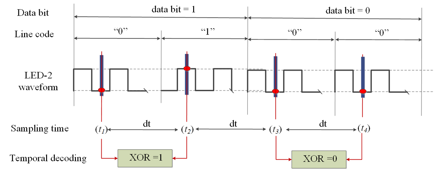
In this case, the camera frame rate is set equal to the optical clock rate. And then, Rx can perform the temporal decoding by comparing two adjacent samplings as illustrated in Figure 4.
The temporal-XOR decoding model is sensitive to the deviation of frame rate (i.e., the variation in the sampling interval). If camera frame rate is varying, this also causes sampling error (called sampling error – type 2).

Besides the RoI signaling purpose, S2-PSK can be used for delivering a short message in case the Tx has a complex multi-LED-structure such as LED-signage. Figure 5 is a capture of our initial demo for using LED-signage to deliver that kind of short message to a typical camera.
In the end, a short demo of S2-PSK for your entertainment!
Conclusion
- The fundamental of the S2-PSK operating mode is reviewed.
- S2-PSK is a flicker-free mode designed for a very short-message data transfer (such as an ID). The modulation scheme is applicable to various types of lighting sources (single LED, multi-LED or even a textured-LED-signage) and compatible with typical cameras (accepting low frame rate camera <30fps, both shutter types of global shutter and rolling shutter are okay). In addition, we implement S2-PSK for the detection and tracking light sources purpose in the vehicular scenario.
- We have some trial demos for the S2-PSK system. Please check out for more demo videos here.